
RTM-Worx User Manual
Geometry and properties
3.1 Entering the Geometry and Properties
3.1.1 Model structure in RTM-Worx
3.1.2 Editing keypoints
3.1.3 Injection and venting ports
3.1.4 Editing curves
3.1.5 Runners and connectors
3.1.6 Editing surfaces
3.1.7 Surface reinforcement properties
In RTM-Worx, a surface model is used to describe the geometry of an object, and each geometry object is automatically subdivided into elements to serve as the mesh for the FEM calculation. The first paragraph gives an overview of the structure of this surface model and the methods available to edit the model are discussed in the remainder of this section.
![[top]](../asp/tp.gif) 3.1.1 Model structure in RTM-Worx
3.1.1 Model structure in RTM-Worx
RTM-Worx provides three basic entities to build the surface model:
- Keypoints to define corners, injection- and venting ports.
- Curves to define edges and runners (optionally filled with UD material).
- Surfaces to define the volumes of the product with or without reinforcement.
An example model is shown below. The keypoints are visible as small spheres and curves are displayed as circular rods. Basically, you define keypoints at specific locations in space by entering (x, y, z) coordinates. Then, you connect the keypoints by curves. Finally, you define surfaces by entering their boundaries as a closed loop of curves. Surfaces are generally flat and have constant thickness and reinforcement properties, so you will have to subdivide the geometry accordingly.
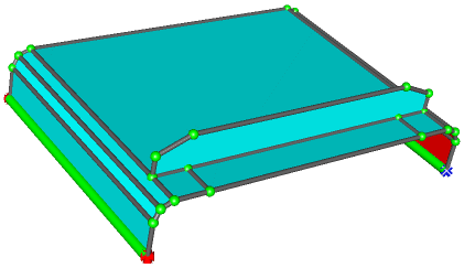
For the flow simulation, it is important that everything is connected. Otherwise, the resin cannot flow from one part to the other. This is different from the way a CAD program treats a drawing where the only requirement are that dimensions are accurate and that the drawing looks good. The geometry editor in RTM-Worx is designed to be flexible and easy to use. It does not replace the functionality of a versatile CAD program but complements it.
Injection and venting ports are defined by adding properties to keypoints. This makes it very easy to change the way the part is injected. You need to define at least one injection point, otherwise nothing will happen if you run the simulation. Venting ports are optional, you can run the simulation without venting ports to find their optimal location.
Curves can be straight lines, but when you use more than two keypoints the curve is smoothly fitted through all the keypoints. You can use this feature to model circular holes for example. You can turn any curve into a runner with or without reinforcement, which means it becomes a hollow tube through which the resin can flow. Because curves are needed to define surface boundaries, you can quickly model the effect of easy flow paths that result from a small gap in between the fabric and the mould wall by changing the curves into runners with a representative diameter. It is even possible to model runners that have negligible resistance and volume to connect surfaces and runners that are not located adjacent to each other (this allows you to model the object like in an exploded view).
Surfaces need at least a thickness to participate in the simulation. You can also define reinforcement properties to model a lay-up with anisotropic permeability. Surfaces don't need to be flat: when the boundary curves are not in the same plan the surface will be doubly curved.
The model does not necessarily very accurately represent the real world object. Because the flow simulation has a global character, not all details need to be included. The orientation of surfaces relative to each other does not really matter, so you can fold out the model if you want. Think of the model (and the simulation as a whole) as a tool in itself. This is emphasized in RTM-Worx by the symbolic display of the entities used to define the geometry. Once you have defined the model, you are free to do anything with it at little cost without doing any harm. This largely outweighs the differences between simulation and practice because the latter only require a little intelligence from you to interpret the results and optimize the real-world process from the information obtained from RTM-Worx.
The shape of the object is defined by (1) location of keypoints in space and (2) the connectivity. RTM-Worx does not restrict the shape in any way. When curves or surfaces intersect without being connected by a keypoint or a curve respectively, this does not influence the calculation. The only restriction regarding the shape of surfaces is that the curvature is restricted by the demand that each point on the surface corresponds uniquely to a single point on it's projection on a flat plane. When this is not the case, you will get an error message from the mesh generator and the surface is not visualized. Solve this by subdividing the surface into smaller parts.
The geometry editor is accessible through the following three control panels:
- Keypoint editor: create, delete, move and copy keypoints. Assign properties to define injection and venting ports. Merge curves by deleting keypoints.
- Curve editor: create, delete, flip, break, split and join curves. Assign properties to define runners which are either empty or filled with UD material. Merge surfaces by deleting curves.
- Surface editor. Create, delete, flip and split surfaces. Assign thickness and optionally properties of the reinforcement.
You can always switch to one of those editors to modify the geometry or properties associated with it. When you have run a simulation, any results from the calculation are automatically deleted when you make a modification. The display and plot settings are adjusted accordingly. For example, if you did select a shaded plot of pressures, RTM-Worx will switch to the default hidden surface plot when simulation results are no longer available but remember your settings and activate them when you rerun the calculation. The three editors will be described in detail in the following sections.
3.1.2 Editing keypoints
You start with building the model by defining keypoints. You need keypoints to:
- Define specific locations, typically the corners of your part and a minimum number of vertices to specify a curved edge.
- Assign injection ports and venting ports, which are actually keypoints with specific properties assigned to them that are needed in the calculation. Any keypoint can be turned into an injection or venting port and vice versa by changing its properties.
- Force local mesh refinement. Adding keypoints on curves will lead to local refinement of the generated mesh, because the mesh size is locally determined by the size of the curve segments. The drawback is that you get badly shaped elements in coarser meshes generated with a lower bound that is larger than the distance between the keypoints.
There are several methods to generate keypoints:
- Enter the coordinates and create keypoints with [Add] in the Keypoint Editor.
- Copy existing points with the [Copy] command at a specified offset in the Keypoint Editor.
- Generate additional keypoints on a curve with the [Split] command in the Curve Editor.
Keypoints are displayed immediately after they are created. If you don't see anything, verify whether keypoint plotting is turned on (render toolbar or Render menu), and check the zoom factor and position.
The Keypoint editor Control panel is shown below:
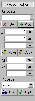 |
List of selected keypoints, used in [Del], [Move], [Copy] and [Apply] commands. The same list is used in the Curve editor. |
| [Del] removes selected points. [Add] adds a keypoint at the (x, y, z) coordinates.. | |
| (x, y, z) coordinates. Enter coordinates here for new points. Updated when you select a new keypoint (without Shift or Ctrl down). | |
| [Move] translates the selected keypoints by the offset (dx, dy, dz). [Copy] creates new points from selected points at the offset (dx, dy, dz). | |
| Offset for [Move] and [Copy] commands. If you select a new keypoint, those fields are updated with the old contents of the (x, y, z) edit fields minus the coordinates of the new keypoint. | |
| Properties are used to define venting and injection ports. Select the property you want to assign to the currently selected keypoint(s) here. | |
| The [Find] command selects all keypoints with specified properties. [Apply] assigns the current properties to all selected Keypoints. |
You can select existing keypoints by typing their numbers in the Keypoints list, or by selecting them by the mouse. Hold down the Shift key when clicking to select multiple keypoints.
If you select keypoints, either by clicking them with the mouse or typing in the keypoint list, the coordinates of the new point are automatically entered in the (x, y, z) edit fields, the (dx, dy, dz) fields are updated with the difference between the old coordinates and the new ones, and the Properties are shown. This automatic updating is not done if:
- You hold Shift or Control down when you select a keypoint with the mouse.
- The keypoint you typed in the Keypoints field is not the first one.
The [Move] and [Copy] commands are only enabled when the offset (dx, dy, dz) is fully specified and no keypoint already exists at the location defined by the selected point(s) and the offset.
If you add a keypoint, it will receive the current properties. Properties for existing keypoints are only updated if you changed them by issuing the [Apply] command. The [Apply] button will be disabled when there is no difference between the displayed properties and the properties of the selected keypoints.
The [Del] command will delete all selected keypoints with the exception of keypoints that are used as end vertex by a single curve or shared by more than two different curves. Two curves that are connected by the keypoint that is deleted will be merged into one single curve. When the curves are part of a surface boundary, they will only be merged when the boundary contains four or more curves. Otherwise, the curves will not be merged, and the keypoint is not deleted. You can work around this by splitting one of the other boundary curves before you delete the keypoint. Those rules make it safe to delete any keypoint without destroying the topology of the model, although it does not guarantee that the geometry represents a valid object, neither are there any restrictions.
3.1.3 Injection and venting ports
Before you run a simulation, you need to define the location of injection ports. Otherwise, when you start the simulation nothing happens! Venting ports, where resin leaves the mold, can also be defined but are not necessary to run the simulation. You might actually want to use the simulation to determine the location of venting ports and any venting ports already defined may undesirably influence the way the part fills. Any keypoint can be used to define an injection or venting port by simply changing its properties. If you want to put an injection port at a location where you don't have a keypoint, create a keypoint by using the [Split] commands in the Surface and Curve editors and move it to the desired place with the [Move] command in the Keypoint editor. For a venting port, you need to define the moment it opens and when it closes. In addition, for an injection port, the pressure and/or flow rate must be defined (otherwise the injection port will behave like a venting port).
| Property | Default | Full name | Remarks |
|---|---|---|---|
| fA | 0 % | Activate at fraction filled | Filled fraction of mold when port opens. |
| fC | 100% | Close at fraction filled | Filled fraction of mold when port closes. |
| Pi | 0 Pa | Injection pressure (maximum) | Pressure at injection port. When it is zero, the port behaves like a venting port, unless a non-zero flow rate is specified. |
| Qi | 0 m3/s | Flow rate (maximum) | Constant flow rate at injection port. When zero, the port behaves like a venting port, unless a non-zero injection pressure is specified. |
Note that the pressure defined at an injection port is actually the pressure difference between injection port and venting ports. The pressure at the flow front and venting ports is set to zero by RTM-Worx.
When both the injection pressure and flow rate are non-zero, both values act as upper bounds:
- If the pressure at the injection port would become larger than Pi (and Pi is larger than zero) at the specified flow rate Qi, a constant pressure equal to Pi is applied;
- If the flow rate at the injection port would become larger than Qi at the specified pressure Pi (and Qi is larger than zero), a constant flow rate Qi is applied.
A closed injection or venting port (mold filled fraction is smaller than fA or larger than fC) behaves like an ordinary keypoint. If you want to vary pressure and/or flow rate during injection, connect a number of injection ports with connectors (see section 2.4.6) and let them open and close in sequence.
3.1.4 Editing curves
Curves are used to define the boundaries of surfaces and to serve as runner channels, for example to model the delivery system or easy flow paths between fabric reinforcement and mould walls. Curves can be created using the following methods:
- With the [Add] command and explicit definition of the list of keypoints in the Curve editor.
- By using the [Split] command in the Surface editor.
You need at least two keypoints to define a curve, but there is no maximum limit to the number of keypoints. If you use more than two keypoints, a cubic spline is automatically fitted through the points. Keypoints on the curve that are not on one of the ends, so called mid-points, cannot be shared with other curves, e.g., you can only connect a spline curve at the ends. If one of the keypoints in the list is already in use by another curve, the [Add] command will automatically split the curve at such keypoints, and if necessary also the existing curve that already used the keypoint.
You can only delete curves that are shared by two surfaces. The surfaces that shared the curve are automatically merged into one surface. When a curve is used by only one surface, or by three or more surfaces it cannot be deleted. You will have to delete the surface(s) first.
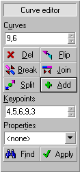 |
List of selected curves, used in [Del], [Flip], [Break], [Join], [Split] and [Apply] commands. The same list is also used in the surface editor. |
| [Del] removes curves and merges surfaces. [Flip] reverses the order of the keypoints on the curve. [Break] turns each curve segment into a straight curve. [Join] merges adjacent selected curves into one spline curve. [Split] generates new keypoints in between existing ones and splits each selected curve in two separate curves. [Add] creates new curves. | |
| List of keypoints for the definition of a new curve. This is the same list that is used in the Keypoint editor. | |
| Properties are used to define runners or to attach numerical tags. Select the property you want to assign here. | |
| The [Find] command selects all curves with specified properties. [Apply] assigns the current properties to all selected curves. |
If you want to approximate a circle or circular arc, use points spaced at 45 degrees or less. The difference between actual radius and the spline approximation will be less than one percent. Note that the accuracy of the spline approximation also depends on the mesh size. If you use a very coarse mesh, the segments of the curve will always be straight lines. Curves will be smoother when a smaller mesh size is chosen.
3.1.5 Runners and connectors
Any curve can be used as a runner by adding properties. In RTM-Worx three types of runners are available:
- Tagged runner. The only property is a numerical tag, no physical properties are present. Used by RTM-Worx when a model is imported for which element group numbers are available. You can use the [Find] command, to select all curves with identical tags and assign one of the following property sets.
- Isothermal runner. This is a tube for which only the diameter is specified.
- RTM runner. This is a channel with circular cross-section that is filled with UD material. In addition to diameter, you need to define the fiber volume fraction and the permeability in the curve direction.
All properties have default values. The diameter defaults to zero, which is allowed and effectively causes the runner to be treated as a curve without properties. The properties are listed in the table below.
| Property | Default | Full name | Remarks |
|---|---|---|---|
| H | 0 m | Diameter | Runner diameter and surface thickness are shared edit fields. RTM-Worx remembers the last value used which makes it easier to choose dimensions. |
| Vf | 0 % | Fiber volume fraction | Equals (1 - porosity). The porosity times the total volume is the space available for the resin. Always zero for an isothermal runner. |
| k11 | 0 m2 | Permeability | The equivalent value for an isothermal runner is D2/32 where D is the inner diameter. |
A connector is a runner element without neither volume nor resistance to flow. You can use it for example to model an exploded view of the part, or to model injection along an edge without having to define the actual feeding system. RTM-Worx does not provide a separate curve type to model connectors, but you can use the RTM runner with properties defined as follows:
- Fiber volume fraction Vf = 99%. The porosity cannot be zero because that would make the runner impermeable. A very small amount of resin will be 'lost', but that is generally not noticeable.
- Permeability K11 substantially larger (about 1000 times) than the permeability of surfaces it is connected to. Don't use values that are too large, because that will lead to loss of numerical accuracy and produce erroneous results (the machine accuracy is about 15 decimal digits).
You may have to experiment a bit with the values for Vf and K11 to get good results.
3.1.6 Editing surfaces
Surfaces are used to model the cavity. By assigning a thickness to a surface it becomes a volume that can be filled with resin.
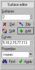 |
List of selected surfaces. Used by the [Del], [Flip] and [Split] commands. |
| [Del] removes surfaces. [Flip] swaps the front- and backside by reversing the order of the boundary curves. [Split] breaks up a surface into a number of smaller surfaces. [Add] creates a new surface from the list of boundary curves below. | |
| List of curves, identical to the one used in the Curve editor control panel. Used to define the boundary of a surface. | |
| Properties include the local shell thickness and optionally the reinforcement porosity and permeability. | |
| The [Find] command selects all surfaces with specified properties. [Apply] assigns the current properties to all selected surfaces. |
RTM-Worx supports four types of surfaces:
- Surfaces without properties. Those surfaces are ignored during the simulation.
- Tagged surfaces. The numerical tag is assigned when models are imported that support element group numbers and can be used with the [Find] command to select groups of surfaces to assign them equal properties. A tagged surface behaves like a surface without properties in the simulation.
- Isothermal shell surface without fabric reinforcement.
- RTM shell surface with thickness and reinforcement properties: porosity and anisotropic plane permeability, which includes the case of isotropic permeability.
A surface is defined by a closed loop of boundary curves that is defined in the list of curves in the Surface editor. The curves have to be adjacent, e.g. each set of two curves in the list must have a vertex in common. The order in which the curves are listed determines the front- and backside of a surface. The front side is defined as the side for which the boundary curves are listed in counter-clockwise order. Once a surface is created, you can always change this order with the [Flip] command.
3.1.7 Surface reinforcement properties
In order to calculate the flow through the fabric reinforcement, it is treated by RTM-Worx as a porous medium with anisotropic in-plane permeability. Because the flow is locally treated as two-dimensional, permeability needs to be defined in two perpendicular directions in the surface plane only. For layers of fabric with different properties, the through thickness average must be specified for the fiber volume fraction and both the magnitude and the direction of permeability. If, for example, even numbers of layers that are anisotropic are stacked 0/90 degrees, the resulting reinforcement becomes isotropic with permeability k11 and k22 equal to the average of minor and major permeability of each individual layer. The properties of the RTM-surface are summarized in the following table:
| Property | Default | Full name | Remarks |
|---|---|---|---|
| H | 0 m | thickness | Field is shared with runner diameter in Curve editor to make it easier to enter dimensions. |
| Vf | 0 % | Fiber/volume fraction | Equals (1.0-porosity). Always zero for an isothermal shell surface |
| phi | 0o | Lay-up angle | Rotation of fabric in-plane relative to the projection of the reference direction. |
| k11 | 0 m2 | Major permeability | Permeability in the main direction. The equivalent value for an isothermal shell surface without reinforcement is H2/12, where H is the distance between the mould surfaces. |
| k22 | 0 m2 | Minor permeability | Permeability perpendicular to the main direction. Equal to k11 for isotropic fabrics. |
| rX, rY, rZ | 1, 0, 0 | Reference direction | (x, y, z) coordinates that defines the direction for the major permeability value, k11. |
The main direction is locally determined on each element by the following procedure:
- Project the reference direction on the triangle (always a flat plane, even on a curved surface).
- Rotate the direction obtained in the previous step by the lay-up angle 'phi'.
There are several ways to visualize reinforcement properties to verify the input:
- Shaded plot of average permeability, defined as (k11 + k22) / 2. This is most useful for isotropic reinforcements. The permeability of surfaces without reinforcement is defined as H2/12 for shell surfaces (H is the distance between the mould surfaces) and D2/32 for runners (where D is the inner diameter) without reinforcement.
- Shaded plot of fiber/volume fraction, which is zero for shell surfaces and runners without reinforcement.
- Vector plot of permeability to display both direction and magnitude. Shows major (k11) and minor (k22) permeability as rods, with length and diameter scaled to the respective value.
- Vector plot of projected reference direction. The magnitude of the displayed vectors equals the cosine of the angle between the plane and the reference direction (rX, rY, rZ).
You can combine the shaded plot of fiber/volume fraction with a vector plot of the permeability to view all reinforcement properties at once. It an also be very helpful to plot porosity of permeability in combination with results (filling time or pressure) to interpret the resin flow.
![]()
home |
contents |
about this manual |
quick start |
introduction
installation |
features |
philosophy |
getting started |
interface |
workspace
menu and commands |
viewing the model |
model and calculation |
mesh generation
simulation
© 1997-2022 Polyworx
![[home]](../asp/pwxpwx.gif)