
RTM-Worx User Manual
Workspace
2.1 The Workspace
2.1.1 RTM-Worx main window
2.1.2 Main toolbar
2.1.3 Render toolbar
2.1.4 Control panel
2.1.5 Display area
When you are building the model, running simulations or viewing properties and results all the tools you need are available with one or two mouse button clicks. In this section, the main window and the how and why it is subdivided in several functional units is explained. Understanding the design of the user interface will make it easier to use RTM-Worx effectively.
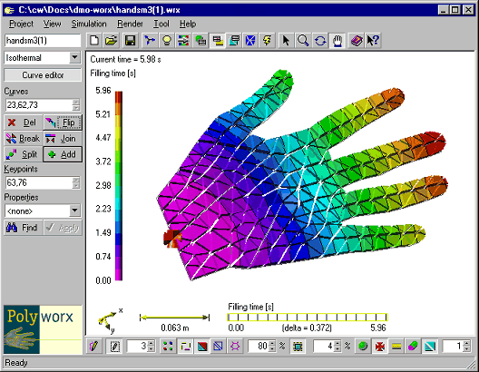
![[top]](../asp/tp.gif) 2.1.1 RTM-Worx main window
2.1.1 RTM-Worx main window
An example of how the RTM-Worx main window may look is shown below. The window has a standard caption bar at the top, a menu and a status bar at the bottom like most Windows™ applications.
The layout is organized around the display of the model. Above and below it are the main and render toolbar respectively. At the left is the Control Panel that contains task-oriented commands and edit fields.
2.1.2 Main toolbar
The main toolbar is located below the menu and contains the commands you need most often. The buttons are logically grouped in sections as shown.
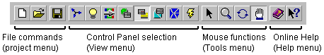
The toolbar not only gives you quick access to those commands, but also shows the currently selected Control Panel and mouse tool. All commands available on the toolbar can be found in the indicated menus and will be explained in paragraph 2.2.
2.1.3 Render toolbar
During modeling and inspection of simulation results, the way the model is displayed is changed often. If and how objects are displayed not only influences selection with the mouse, but also the scaling of results. Therefore, a special toolbar is available (and visible by default although it can be hidden like the main toolbar) that makes the switches and settings that influence the model display quickly accessible and shows at a glance what the current settings are:
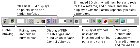
All the buttons are also available as menu commands in the Render menu. The edit fields from the left to the right are listed in the table below.
| Short name | Default | Description |
|---|---|---|
| Point size | 3�pixels | This setting influences (1) the size of the flat squares plotted at keypoints and (2) the size of the imaginary tube around a curve or runner displayed as a line in which you can select it with the mouse. If you turn on 3D curves and/or runners, this value defines the minimum diameter in which you can select with the mouse. Don't use large values, because the relation between mouse cursor position and what you select will get lost. |
| Element size | 80% | The Finite Elements displayed as triangles on surfaces and circles around runners are shrunken by this factor. A value of 100% results in no shrinkage and the edges of adjacent elements coincide. This value is also used as the shrinkage factor for 3D runners, curves and shells where a value of 100% gives results in a display identical to turning shrinkage of 3D objects off. |
| Symbol size | 2% | Size of symbols relative to the model size (defined as the diameter of the smallest sphere the geometry will fit in). The resulting size is used as the radius of keypoint symbols and the diameter for ordinary curves displayed as 3D tubes. |
| Scaling factor | 1 | For the display of 3D runners and surfaces, the diameter or thickness respectively is multiplied by this value. It allows you to check correct modeling of small thickness differences. |
2.1.4 Control panel
The control panel is located at the left edge of the RTM-Worx window. The width is variable: you can drag the right border with the mouse. This can be useful if you are using the keyboard to enter a list of numbers, or when you like to work with buttons that contain both bitmaps and text.
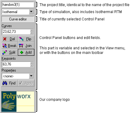
You can edit the project title directly. If you finish with pressing Return, the project name and the name of the current project file will be changed.
The simulation type can be changed to Isothermal RTM. The Isothermal RTM provides a common basis for simulations in all CFD-Worx based applications. If you select a different simulation type, any simulation results will be deleted and the model is automatically converted. Note that all reinforcement properties will be lost when you convert a model from Isothermal RTM to Isothermal.
The variable part of the Control Panel is where you can access commands and parameters for specific tasks. When the RTM-Worx window is too small to display the entire panel, it will auto-scroll vertically when you move the mouse to the top (just below the title) and bottom (just above the PolyWorx company logo), or when you use the Tab key to move around the panel.
Each Control Panel has a default button, indicated by a black border. Pressing the Return key executes the command associated with the default button. Unlike the behavior in dialog boxes, the Default button does not change with the keyboard focus: pressing Return always executes the same command. You can press a button that has the focus (indicated with a dashed rectangle) with the Spacebar.
Accelerator keys on the Control Panel are underlined and are used pressed together with both the Alt and Control keys down. For example, the keyboard shortcut for the [Add] button is Ctrl+Alt+a.
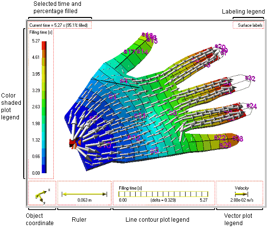
2.1.5 Display area
The largest part of the screen is used to display the model. It also includes object coordinate axes to indicate the orientation of the model and a ruler that measures the scale. The ruler size is averaged if perspective projection is used. Current time and percentage filled are shown in the upper left corner when results are available from a simulation. Legends are added where applicable for shaded color plots, line contour plots, vector plots and labels respectively.
RTM-Worx offers a lot of flexibility for the display of the model. Basically, you can change options and parameters for the following four conceptually separate groups of settings:
- View direction and scale. The model can be rotated and scaled (called zooming) and you can move it around (panning or scrolling). The object coordinate axes and ruler reflect current settings.
- Appearance (light, color and reflectivity). You can choose the spotlight direction, the amount of ambient light, depth attenuation and colors for the background, text, lines and symbols to get a clear picture of your model. This is especially important to avoid ambiguities that easily result from displaying a three dimensional object on flat and relatively small computer screen.
- Rendering options. Based on the way the model is defined in RTM-Worx, you can selectively display points, lines, surfaces and mesh either classical (flat 1D) or symbolically (3D symbols). This allows a symbolic display, easy during editing, but also a realistic display of your part.
- Properties and result plots. You can choose any combination of shaded contours (uses colors from a palette that correspond to different values), contour lines and vector plots to display properties like thickness and permeability and results like flow fronts and pressure.
The table below summarizes the parameters and settings you can change and where to find them in RTM-Worx. The last column specifies the corresponding section in this manual.
| Display change | Where to control display in RTM-Worx | Section |
|---|---|---|
| Points, lines, hidden surface, wire frame, elements etc. | Render Menu or Render Toolbar (below model display). Independently select classic or 3D display of points, lines, surfaces, elements and nodal control volumes. | 2.1.3 |
| Rotate, zoom, pan | Model View Control Panel for numerical values and button. Tool menu (or buttons on main toolbar) to use the mouse. | 2.3 |
| Light and color | Appearance Control Panel. Set ambient light, depth attenuation, spotlight direction, reflection properties and colors. | 2.3.5 |
| Labels | Plot Selector Control Panel. You can display keypoint, curve surface, node and element labels. | 2.3.6 |
| Time, fraction filled | Plot Selector Control Panel. Step through time (manual animation) or select specific time step. | 2.3.6 |
| Color contours | Plot Selector Control Panel. Select property or result to plot, number of colors, color palette, and optional nodal smoothing. | 2.3.6 |
| Contour lines | Plot Selector Control Panel. Select result to plot, number of contour lines and optional color palette. | 2.3.6 |
| Vector plot | Plot Selector Control Panel. Select property or result to plot, scale for arrows and upper limit. | 2.3.6 |
![]()
home |
contents |
about this manual |
quick start |
introduction
installation |
features |
philosophy |
getting started |
interface
menu and commands |
viewing the model |
model and calculation
geometry and properties |
mesh generation |
simulation
© 1997-2022 Polyworx
![[home]](../asp/pwxpwx.gif)