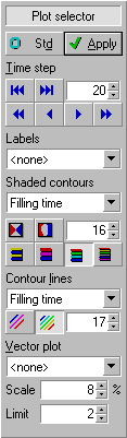
Display of properties and results
 Because all postprocessing functionality is available even when no
simulation has been done yet, several plot options are available to verify the correctness of the
model. Any combination of shaded contour plots with vector plots and numerical labels can be
selected.
Because all postprocessing functionality is available even when no
simulation has been done yet, several plot options are available to verify the correctness of the
model. Any combination of shaded contour plots with vector plots and numerical labels can be
selected.
The simulation calculation generates a huge amount of data. Interpretation of the results is done
using a combination of the following flow visualisation methods:
- Shaded contour plots of pressure and filling time;
- Line contour plots of pressure and filling time;
- Vector plots of velocity;
- Animation of the flow of the resin.
Shaded plots can be combined with line contours and vector plots and mix them with display of
all properties mentioned earlier. Actually, having calculation results only increases the plotting
options you can select from.
Numerical labels.
The program maintains numerical labels for keypoints, curves, surfaces, line elements on runners
and triangular shell elements on surfaces. Those numerical labels are optionally plotted using a
3D font (any TrueType™ font installed on your system can be selected). The 3D labels are
'glued' on the 3D objects they belong to.
Shaded contour plots.
In shaded contour plots, properties or results are visualised by using different colours to
draw the surfaces where colours correspond to a range of values. Four palette types are available,
with a palette size in the range of 2 to 256 different colours. The direction of the light and
reflective properties of the surface are taken into account in shaded plots to ensure that the 3D
shape of the part stays clearly visible. You can choose to display the following properties:
- Thickness of surfaces and diameter of runners.
- Tag numbers, which are used when FEM models are imported that have element group numbers
assigned to elements.
- Fibre volume fraction in runners and surfaces
- Permeability of runners and the average of major and minor permeability on surfaces.
- Triangle quality (length of the shortest edge divided by the length of the longest edge).
- Obtuse triangles where prediction of the flow front is less accurate.
- Connectivity count that is defined for keypoints as the number of curves that use it, and for
curves as the number of surfaces using it as part of their boundary.
When a simulation has been run, the following results can also be displayed in a shaded contour
plot (the list with selections will contain those items when available):
- Flow fronts, including potential air-traps and dry spots.
- Pressure during filling (see example).
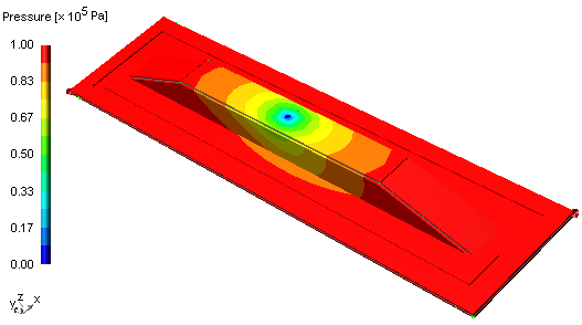
Line contour plots
An alternative way to display results is plotting lines for a limited set of values, like
isobars for the pressure. You can use a single colour to display the lines, or use a colour
palette similar to the colours used in shaded plots. Line contour plots are available for:
- Flow fronts, potential air-traps and dry spots are displayed as closed contours.
- Pressure during filling (isobars).
Line contour plots can be used in combination with shaded plots to display results together
with properties to aid in the interpretation of the simulation. You can also use contour lines to
enhance shaded plots by displaying the same property or result as both a shaded and contour line
plot with an equal number of colours.
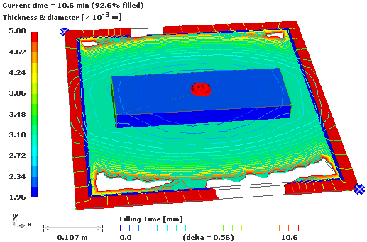
The example plot shows how you can combine a shaded plot of a property (in this case the
thickness) with a contour plot of a simulation result (here the filling time).
Vector plots
Properties and results that not only have a magnitude but also a direction are best visualised
using arrows, or rods (permeability). You can view the following properties as a vector plot:
- Permeability. Displayed on runners as arrows, and on surfaces in two directions as rods; the
magnitude of the permeabilities is used to scale both the length and diameter.
- Reference direction. This is the direction (specified in x, y and z coordinates) relative to
which the major and minor permeabilities are defined and is plotted as arrows.
When a simulation calculation has been run and results are available you can also display:
- Resin velocity. Displayed as arrows on each runner and surface element.
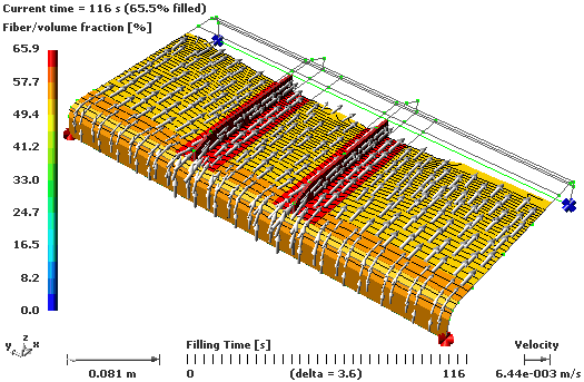
This plot shows a combination of a vector plot of the resin velocity, which clearly shows how
the resin flows with a shaded plot of the fibre/volume fraction and a contour plot of the filling
time. Fibre/volume fraction is important to understand 'strange' differences in velocity.
The filling pattern is a result of a history of velocity fields for the resin flow.
home |
introduction |
requirements |
user interface |
geometry editor
material and process data |
mesh generation |
file system |
calculation
© 1997-2022 Polyworx