RTM-Worx Geometry Editor
A 3D surface modeller is integrated in RTM-Worx. Parts are assumed to be thin-walled and
described by the mid-plane of each surface.
 The x, y
and z coordinates of the so-called 'keypoints' which define the vertices of a mid-plane
surface are first entered. The edges of a surface can then be described by connecting keypoints as
'curves'. A surface is made up of a closed set of consecutive curves. Each surface has a
thickness and fabric properties as attributes.
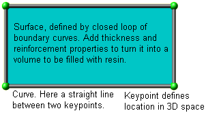
Perhaps the simplest product imaginable is shown here as an example. It is a rectangular plate,
and keypoints, curves and the surface are clearly visible. Sure, this is not a realistic rendering
of a product. Of course, RTM-Worx alows you to plot in a realistic way, but that is not what you
will want to work with. The emphasis is on a symbolic representation that clearly indicates the
structure of your model and makes it easy to edit it interactively.
Assigning properties like thickness and optionally porosity and permeability to curves creates
so-called 'runners'. These can not only be used to model the delivery system, but also to
model easy flow paths. Runners can be used wherever a curve is allowed.
Injection ports and venting points are defined by assigning properties to keypoints.
The physical size of the model is only limited by the range of single precision floating point
numbers (approximately 1e-38 to 1e+38 meters). The number of keypoints, curves and surfaces is
only limited by the amount of RAM available.
Importing data from other applications
RTM-Worx is capable of importing the following file formats:
- AutoCAD DXF; both 2D and 3D models, up to r14.
- PATRAN Neutral File format (mesh imported as surface model).
- PATRAN/Laminate Modeller Layup file (available separately).
- STL (3D Systems Inc. SLA Interface) files, binary and ASCII formats.
- C-Mold mesh file (fem), imports mesh and properties as surface model.
- SEPRAN mesh (.msh) files, including connection elements.
- p7 Model Database (.pi7) files: full implementation.
More formats can be added upon specific request. The data imported is converted to a RTM-Worx
geometry model to allow editing the part geometry using the surface modeller without restrictions
and to add thickness, diameter and fabric properties. For FEM formats, element group numbers are
turned into so-called 'tags'.
Using the integrated surface modeller


 Three control
panels are used to enter and change the geometry, part properties and location of injection and
venting ports. The basic commands for each panel are:
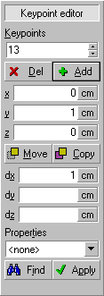
- Keypoint editor: add, delete, move and copy. Deleting a keypoint shared by two curves
will merge the two curves.
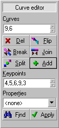
- Curve editor: add, delete, flip, break, join and split. Deleting a curve shared by
exactly two surfaces will merge the two surfaces into a single one. The direction of the curve is
changed by the 'flip' command; the split command will double the number of segments on a
curve, creating a new keypoint in between each set of existing keypoints. Join merges a number of
curves into a cubic spline, while break splits a cubic spline into straight line segments.
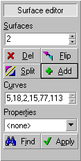
- Surface editor: add, delete, flip and subdivide. The 'flip' command reverses
the orientation of the surface. The 'subdivide' command replaces a surface by the smallest
number of triangular surfaces possible.
All geometry editors allow type selection, definition or change of properties and selecting all
objects with the same properties automatically.
home |
introduction |
requirements |
user interface
material and process data |
mesh generation |
pre- and postprocessing
file system |
calculation
© 1997-2022 Polyworx
 The x, y
and z coordinates of the so-called 'keypoints' which define the vertices of a mid-plane
surface are first entered. The edges of a surface can then be described by connecting keypoints as
'curves'. A surface is made up of a closed set of consecutive curves. Each surface has a
thickness and fabric properties as attributes.

 Three control
panels are used to enter and change the geometry, part properties and location of injection and
venting ports. The basic commands for each panel are: